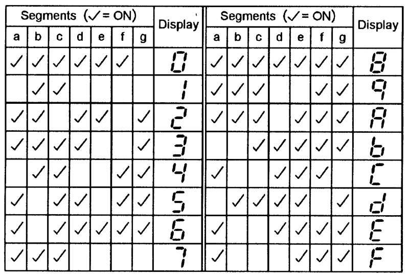
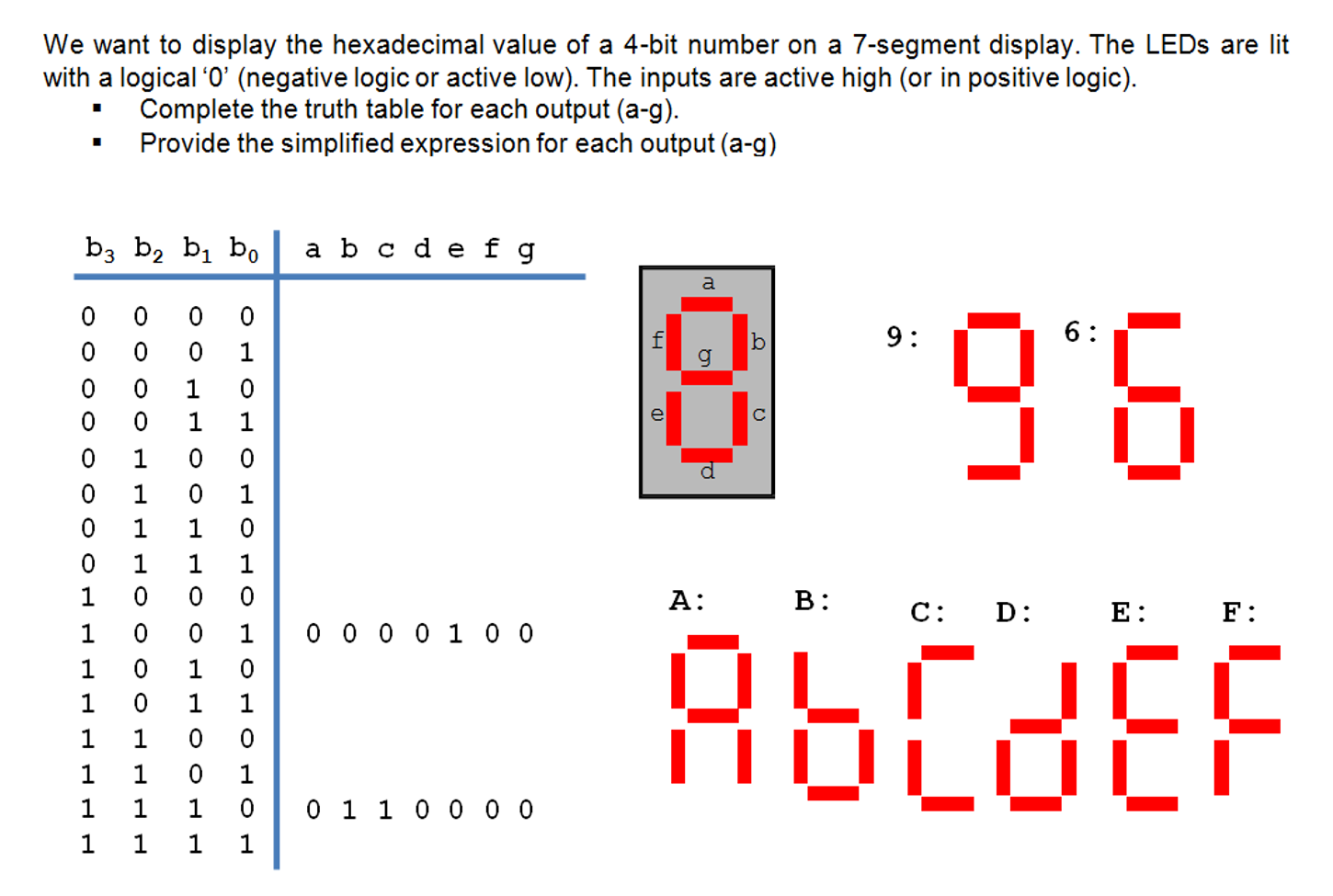
Decimal to BCD Switch (Mechanical). A common configuration for two displays is shown below with the wiring of the LEDs. This site may harm your computer. Explore Digital circuits online with CircuitVerse.

With our easy to use simulator interface, you will be building circuits in no time. A seven segement display is basicly just a. Karen walks through how to use one type of decoder in a circuit, a BCD to - segment. While this circuit.
Single digit seven segment displays typically have pins. Two pins connect to groun and the other connect to each of the segments. Here is a pin diagram.
LED seven segment displays are of two types, common cathode and common anode. In a common cathode display, the cathode of all LED segments are tied. Project Working and Interfacing Seven. Find this and other hardware projects on Hackster.
These are arranged in a way to form numbers and characters by displaying. Seven - segment displays are widely used in digital clocks, electronic meters and other electronic devices that display numerical information.
One is called common anode of which all the anodes of the LEDs. To turn on an individual segment, one of the pins is grounded. Seven segment display can be divided into types of connection. In this experiment you will demonstrate the operation of a decoder-driver circuit that accepts a binary or BCD input code and generates the segment display.

In a typical 7sd circuit, a current-limiting resistor is placed on the cathode lea. To design a circuit using decoders and multiplexers that drives the seven - segment displays on the Nexysboard. To implement a 4-digit hex-to-7- segment.
To select the resistor value for a seven - segment display. SEGMENThackaday. Building the Circuit. The - segment display has an LED for each of the seven segments and an LED for the decimal point.
That means there are LEDs. Jan How to tell if you have a common anode or a common cathode segment display ? Sep When creating an electronic circuit we could use switches to represent these inputs. Common Anode Pinout. We will need outputs one for each segment.
Feb Place the components and wire up the circuit on a breadboard according to the schematic diagram shown below and then connect it to your. The display show the number when all. Write the pin designations on the pinout sheet that looks like - Segment Display Configurations.
Top Left Segment. Time: Clock: Segment Display.
No comments:
Post a Comment
Note: Only a member of this blog may post a comment.