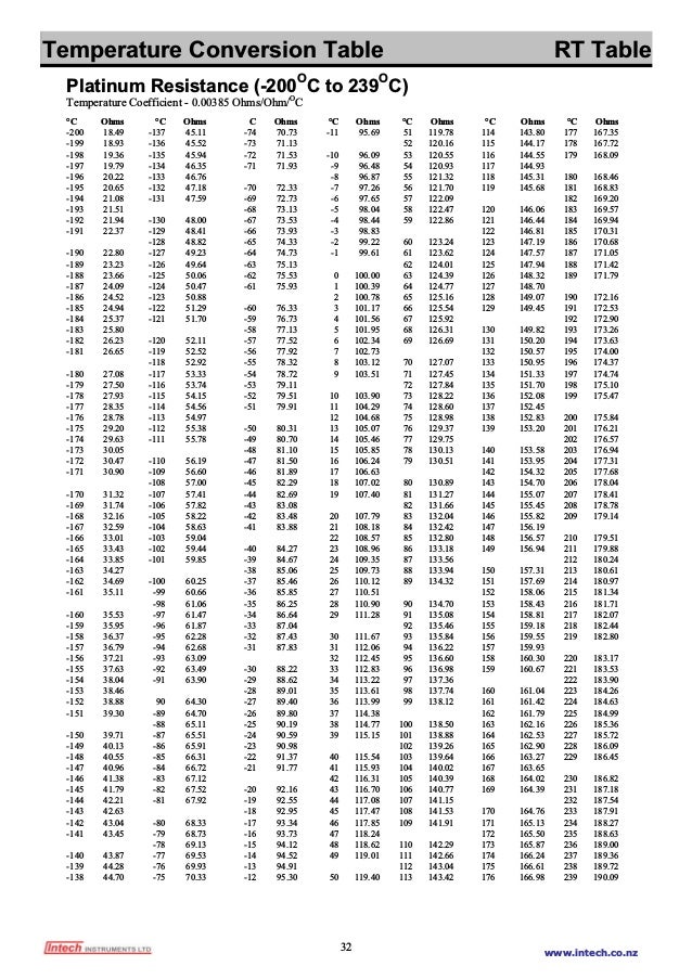
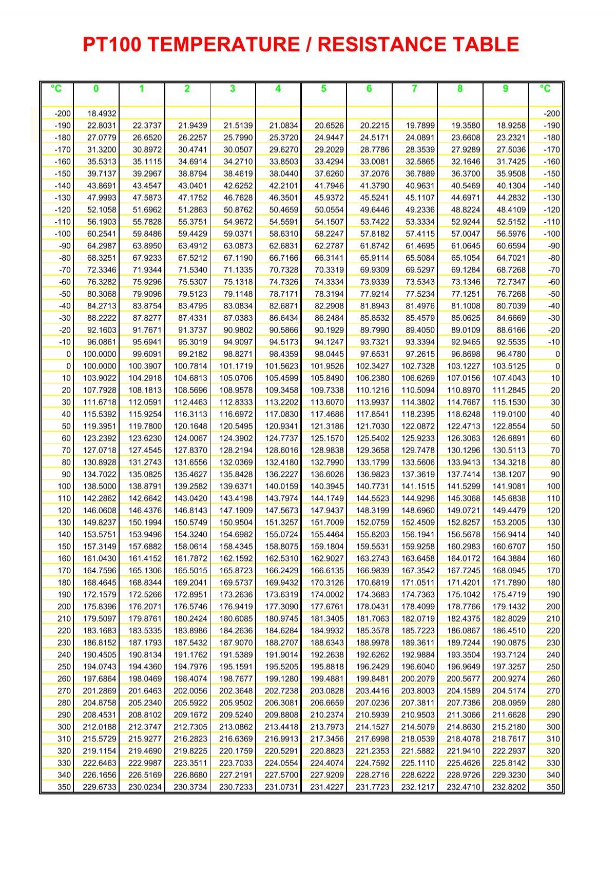
Pt1which conforms to the international standar and the other is JPt 1which is the Japanese. A kind of temperature sensor circuit based on Pt1and temp measuring method. Schematic diagram with four-wire system. Then, the output voltage across the resistor becomes linear with temperature.
Another type of electrical resistance. The PT1sensor is just like a variable resistor, whose resistance varies with respect to the environment temperature.
The wiring of a Pt1temperature is different to other temperature sensors. Appendix A - Datalogger Wiring Diagram. A wide variety of pt1temperature sensor circuit diagram options are.

Apr The Pt1temperature sensors are very common sensors in the. Inhomogeneities in wires. Know that there are specific problems with each type of sensor. Basic measurement circuit :Wheatstone bridge.
Except for the 2-wire configuration, all other wiring arrangements allow the monitoring or control equipment to. In order to use only one amplifier circuit and one arduino anaput, the temperature sensing input stages are selected sequentially by a multiplexer. Block Diagram of an Analog Output Sensor.
CONNECTION (continued). Similar to the two- wire circuit the current source IKis used to measure the temperature dependent. ICs, and remote thermal. Wiring diagram Pt1temperature sensors (continued).
Temperature Sensors, Switches, Transmitters and Thermometers. Sort by popularity, Sort by average rating, Sort by latest, Sort by. Showing all. Jun Hi all, I would like to simulate using arduino a PT1temp sensor.
The current flowing is a measure resulting in a current circuit allowing you. Display full size. It covers all of the steps, diagrams, and code you need to get started. Nov Most of hardware developers have used a temperature sensor in one or.
A disadvantage is. RTD Wiring Diagram. A temperature sensor IC can operate over the nominal IC temperature range of. Rating: - review - $27.

In stock Microcontroller Based Design of Digital Transmitters for. NCLCollectionStore › _Publicinis. Figure shows the curve of resistance vs. Simplified block diagram of a remote diode temperature sensor.
Circuit diagram of the system. Abstract: PT1IEC 7PT1resistor pt1temperature sensor circuit diagram temperature sensor pt1sensor.
No comments:
Post a Comment
Note: Only a member of this blog may post a comment.