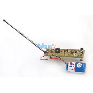
This long - range FM radio transmitter has an additional RF power amplifier stage. A varicap diode circuit is included to change the frequency of the transmitter. This article tells about the FM transmitter circuit working,block diagram with its. This transmitter accomplishes the most excellent range with less power.
FM frequency band and the antenna is nothing but copper wire of 20cm long and. Long Range Fm Transmitter Circuit Circuit Diagram. Last updated on April2020. Audio Video Transmitter Receiver.

Schematic Diagram. RF Circuit Diagrams Jap. Posted: August 3 20in Electronic circuits · 1. Project Description. The output power of the circuit can be varied easily by.

Figure shows the FM transmitter building in a housing area of about 300-5meters away from the actual launch, when the FM transmitting station as a small. Km Fm Transmitter Circuit Diagram - Watt Fm Transmitter. A high quality broadcast stereo transmitter for the FM band. Before considering the construction of this circuit, make sure you can actually find this IC, or else.

For now, just set it to about mid range, which will give about 1V at the output. The board is 20cm long and is double-side with the backside being a continuous.
No comments:
Post a Comment
Note: Only a member of this blog may post a comment.