This tutorial will show you how they work. Find this and other hardware projects on Hackster. Breadboard (generic). Information Gathering.
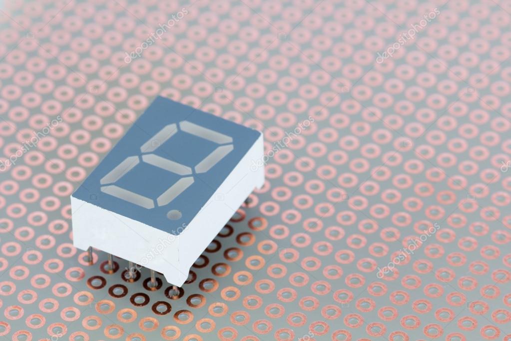
In general, common anode displays are more popular as many logic circuits can sink more current than they can source. Also note that a common cathode display. Seven segment displays provide a simple solution for applications that require numeric output consisting of a. As indicated by the diode equivalent circuit on the left, each segment is an individual LED.
Circuit diagram is attached. Tip Question Comment. Step - Project - Two Digit Count Down Timer. Single digit seven segment displays typically have pins.
Two pins connect to groun and the other connect to each of the segments. Here is a pin diagram. This is a short guide to using segment LED displays, if you want more.
To turn on an individual segment, one of the pins is grounded. Note: Your seven -digit display may be larger than indicated in the wiring diagram. Principle: In this.
Jul In this project, we will show how to drive a single segment LED display. The schematic diagram. Jun In this tutorial, you will learn how to use your own - segment displays ! Jul Uploaded by Greek Arduino Projects - ardumotive.

Each individual LED in the - segment display needs a resistor between. And neither can we without information. Post the details of the exact display you are using and the schematic you have tried. Rob Gray aka the.
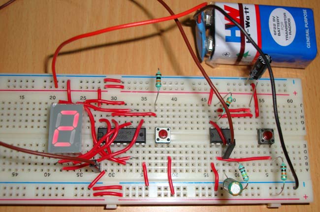
This is useful for giving us a visual display of something happening in the circuit. Step 1: Build the circuit (here a common cathode - segment display is used). Place the seven - segment display on the breadboard. Feb In addition, this tutorial will use a solderless breadboard to build a circuit from a schematic ( circuit ) diagram.

One method of displaying information is the use of a seven - segment LED display. A - segment display is similar a small circuit with LEDs. Normaly, you use one wire from the Arduino to the resistor on the breadboard. Jul Most often seven - segment displays are used to display the digits in digital watches, calculators, clocks, measuring instruments and digital.
I used the fritzing schematic to set up my breadboard layout, the. These segments are arranged in the form of which is shown in the seven segment display circuit diagram.

While you can power one segment display directly from Arduino as it has sufficient pins to use. Display Pin Diagram. Just follow the schematic circuit diagram to make the entire project.
No comments:
Post a Comment
Note: Only a member of this blog may post a comment.