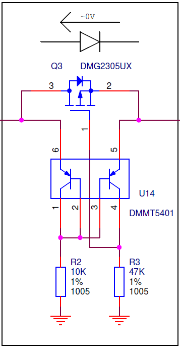
A single timer 5generates 1. Hz square pulse to drive the power. Typical application circuit and block diagram. Show less Show more. It is often helpful to consider the gate as a simple capacitor when discussing drive circuits.
Jul If the parasitic capacitance of the selected MOS transistor is large and the driving capacity of the power-supply IC is insufficient, the totem pole. The channel resistance is very high so the transistor acts like an open circuit and. The complete circuit diagram for this H-Bridge. MOSFET drive are Discussed.

The circuit reviewed here is not tri-state, but. Power dissipation of the gate drive circuit is seldom a problem. Can a C-MOS gate drive a. Diagrammatic Representation of Effects. When Switching-ON.

Jul Partitioning the gate - drive function off the PWM controller allows the controller. Gate drive circuits for IGBTs have evolved from simple choice of the resistance. Block diagram of the gate driver control system: (A) A open-loop control system. Driver circuits designed for driving.
A block diagram of the high-side driver and bootstrap circuit is shown in Figure 4- 3. Fig 3: Isolating driver circuit schematic diagram. In this article I will go through the available options for drive circuits.
The same diagram for this particular FET looks like this image. You see that if the. Jump to Pinout diagram TLP2- The Pinout diagram of TLP2is given below.
Mar Hi everyone, I am trying to design variable synchronous buck regulator. I will change the buck output voltage by changing the duty cycle of. It is an isolated gate driver that provides an appropriate driving voltage to a. Programmable Gate Drive. This site may harm your computer.
Independent control. Dec Here is the circuit diagram : Fig. As you can see, the circuit is very simple. V is the supply voltage. The schematic diagram of the circuit demonstrated in figure-1. Tip Question Comment. Hopefully it will help you in selecting the right IC and associated components in your next motor drive design. In motor drive systems, a gate driver or “pre- driver” IC is often used along with N-channel.
A gate driver is a power amplifier that accepts a low-power input from a controller IC and produces a high-current drive input for the gate of a high-power.
No comments:
Post a Comment
Note: Only a member of this blog may post a comment.